
DIY Greenhouse Control Box Build Using a Raspberry Pi
Intro
This is a guide to recreate the control box unit I have built for my grow space, lovingly dubbed THE REGULATOR. When I started this project, I had zero experience with: the Raspberry Pi, Linux, python, JavaScript, Node-RED, any kind of web or network interface, or even breadboarding. What I did have rudimentary experience with: basic electronics & circuit design, AC voltage wiring, other programming languages (C++, VB, MATLAB, MS-DOS). While creating the box, I searched for a lot of guides and surprisingly found no one had attempted (or accomplished) what I was out to do - automate the basic functions of my grow space and provide a way to remotely monitor and control the system. It needed to use minimal programming languages which have to interface with each other, and tech savvy gadgets. So, I pulled together the best tools I could find and applied them to growing. I wanted to document what I did in hopes that others who are trying to do the same can have a reference. Or that others who may have thought this project to be beyond them would see it is doable if you’re willing to learn.
At this point in development, the control box has the following functionality:
- Monitoring & charting Relative Humidity, Temperature, and calculated VPD
- Monitoring & charting of reservoir liquid level (optional)
- Manual on/auto and kills witch controls for all devices + master kill switch
- Status indicator "lights" for all relay outputs
- Light timer, override-able with user input times
- Light Dimmer slider (requires PWM-compatible driver) with calculated wattage gauge (not a wattage meter)
- Upper and lower limit settings for temperature and RH
- High RH activates exhaust (built in dead band to avoid exhaust/humidifier bounce), deactivates humidifier
- Low RH activates humidifier, deactivates exhaust
- High temperature activates exhaust (overrides Low RH)
- Low temperature deactivates exhaust (does not override Low RH)

This guide is geared toward the novice, but not the totally inexperienced. I will assume you have some basic knowledge about electronics, especially AC wiring (seriously, do not mess with AC wiring if you don’t know what you’re doing), basic programming logic/flow, and soldering. I trust anyone who tries to follow this guide will use some common sense. I won’t pretend like this build is optimized for ease or cost - it is just a recreation of what I have made and I am wide open to suggestions and corrections. As a disclaimer, I take zero liability for any damage or injury to you, your plants, or whatever location you implement this design. I am still a novice myself and cannot provide you troubleshooting help or support.
With that out of the way let’s do this. First, here’s what you will need - one of each unless described otherwise:
| Description | Link/Source | Cost |
| Pi starter kit w/ NOOBS pre-loaded. Has everything needed to get started. | https://www.amazon.com/gp/product/B0748NK116 | $34.99 |
| MOSFET modules for PWM dimming of the driver(s) - kit includes 2 modules | https://www.amazon.com/DGZZI-Transistor-Trigger-Regulator-Electronic/dp/B07PT4MMCK/ | $7.99 |
| Solderless breadboard, for pre-assembly and testing of electronics. OPTIONAL IF you are confident with soldering all connections to the permanent breadboard (below) | https://www.amazon.com/gp/product/B072FC35GT | $5.97 |
| Half sized solderable breadboard, for making connections permanent. | https://www.adafruit.com/product/1609 | $4.50 |
| 50 ft Ethernet cable, to be stripped and used for wire | https://www.amazon.com/gp/product/B01HI5SXZI | $6.25 |
| 10" x 6" x 4" enclosure box to house control modules & Pi | https://www.amazon.com/gp/product/B0786ZT7G3 | $16.99 |
| 8 channel 5VDC relay board for 110V devices - to control all AC devices like lights, fans, humidifier, etc. | https://www.amazon.com/gp/product/B01NBUDHPB | $8.59 |
| DHT22 temperature & humidity sensor module with necessary resistors/capacitors built in | https://www.aliexpress.com/item/1set-DHT22-single-bus-digital-temperature-and-humidity-sensor-module-AM2302-electronic-building-blocks/32852519897.html?spm=a2g0s.9042311.0.0.17824c4dql4iIA | $2.57 |
| Kit of dupont jumper pins, perfect for breadboarding and acceptable for soldering | https://www.amazon.com/gp/product/B07F1PG5QV | $9.99 |
| 5 connection Wago nuts, for connecting AC wires, 10 pack | https://www.amazon.com/gp/product/B06XH47DC2 | $8.95 |
| 15A Outlets (x5) | https://www.homedepot.com/p/Leviton-Decora-15-Amp-Residential-Grade-Self-Grounding-Duplex-Outlet-Light-Almond-R56-05325-0TS/202066687 | $10.95 |
| 4 outlet face plate | https://www.homedepot.com/p/Leviton-4-Gang-Decora-Rocker-Switch-Wall-Plate-Light-Almond-80412-T/301349140 | $1.90 |
| 1 outlet face plate | https://www.homedepot.com/p/Leviton-Decora-1-Gang-Wall-Plate-Light-Almond-R59-80401-00T/100669048 | $0.49 |
| Wire Strain Reliefs | https://www.homedepot.com/p/Halex-3-8-in-Non-Metallic-NM-Twin-Screw-Cable-Clamp-Connectors-5-Pack-20511/100133208 | $1.71 |
| 14ga solid core wire - red - 50ft | https://www.homedepot.com/p/Southwire-50-ft-14-Red-Solid-CU-THHN-Wire-11581683/204834084 | $10.17 |
| 14ga solid core wire - black - 50ft | https://www.homedepot.com/p/Southwire-50-ft-14-Black-Solid-CU-THHN-Wire-11579083/204834040 | $10.37 |
| 14ga solid core wire - green - 50ft | https://www.homedepot.com/p/Southwire-50-ft-14-Green-Solid-CU-THHN-Wire-11583283/204834085 | $10.17 |
| 20A 14ga cord w/ 3 prong plug | https://www.homedepot.com/p/Husky-9-ft-14-3-Power-Tool-Replacement-Cord-AW62632/100661452 | $12.97 |
| Misc: electrical tape, resistors, solder, double sided foam tape, terminal blocks/wire nuts/wagos | ||
| Total | $165.52 | |
| Tools Required | ||
| Needle nose pliers | ||
| Screwdriver (Phillips & Flathead) | ||
| Dremel w/ cutting bit | ||
| Soldering iron | ||
| Wire cutters / strippers | ||
| Keyboard, mouse, and HDMI monitor | ||
| Computer on the same network as the Pi | ||
| Optional Upgrades | ||
| https://www.aliexpress.com/item/HY-SRF05-SRF05-Ultrasonic-ranging-module-Ultrasonic-sensor-Quaranteed/32810476490.html?spm=a2g0s.9042311.0.0.574a4c4dWybsSI | HY-SRF05 SRF05 Ultrasonic ranging module Ultrasonic sensor for reservoir sensor - will require two additional resistors to avoid damage to the Pi! See guide for details. | $0.99 |
| https://smile.amazon.com/Raspberry-Complete-Starter-Cooling-Heavy-Aluminum/dp/B07BDQZ2TB | Raspberry Pi Model 3 B+ starter kit - HAS BEEN SUPERSEDED BY THE MODEL 4, kits available ~8/15/19 | $79.99 |
There are many commonly owned materials on the list which can significantly cut down on the cost of the project - copper wire, for example. Beware substitutions (like alibaba or ebay equivalents) at your own risk.
Step 0: Tips
- READ THIS ENTIRE GUIDE BEFORE PURCHASING ANY PARTS OR ATTEMPTING ANY STEPS. I cannot stress this enough. If you read through this guide and it seems too complicated, you should probably hold your horses and do some more reading or practicing on the fundamental subjects. You also may read something that confuses you, but makes sense once you read subsequent steps.
- Step headings contain links to the guides I used when finding my way through this project. They helped a lot and that is why I linked them. They said it better than I possibly can so use them - I will provide specific insight where I can from a novice’s point of view.
- Remember to run wires through the control box housing as you are building the unit, or plan on building outside the box, then rebuilding inside it. I encourage building outside the box for those who are less experienced.
- Make permanent wire connections when your design is finalized. Solder wires in place, use screw terminals, wire nuts, wagos, etc. Do not twist wires together and cover in electrical tape, do not leave all your wires plugged into a breadboard, etc… this only causes intermittent and inexplicable behavior for the control box at best, or catastrophic shorts, failure, or fire at worst.
- You may want to opt for the more powerful Raspberry Pi Model 3 B+ [Note: as of 6/24/19 the Model 4 has superseded the Model 3 B+, however I have not attempted to build nor run this program on either Model 3 or 4 and make no guarantees for its compatibility] for this application. My original intent with the Pi was to run basic python scripts, but as I learned it was capable of much more, I wanted to add that functionality. At times, the Pi Zero may bog down, the dashboard web page may be unresponsive for a few seconds, etc. and you cannot run the Chromium browser via the desktop UI while also hosting the Node-RED server since the Pi Zero does not have enough RAM. I personally believe that a Model 3B+ or a Model 4 could run the Node-RED server, the desktop UI, Chromium browser, and VNC server with ease. This would make the UI accessible from any device, anywhere with an internet connection.
Step 1: Assemble the Pi kit
Solder the header pins to the Pi if needed. Put the SD card in, plug in the power, the USB hub, the keyboard and mouse, monitor, and boot up the Pi.
Step 2: Install Raspbian OS
Use NOOBS to install Raspbian operating system. You can opt to use a desktop interface if you’d like, but if using a Pi Zero you will not be able to both host the Node-RED server and use a browser on the Pi to edit it very effectively due to RAM and CPU constraints. The desktop UI may still be easier for newer users to navigate during installation, and can be disabled at boot-up to preserve RAM once installation is complete. Enable SSH access as well, using the "raspi-config" command from the prompt.
Step 3: Connect to the network/wifi
This might even come before step 2, but by the time you get to the desktop you should be able to set up network connections, either hardwired or wifi. Find your local network, and connect to it.
Step 4: Install Node-RED
Some installations of Raspbian have Node-RED installed by default, from what I’ve read. If you have it installed, skip to the part in the linked guide where it shows how to launch the Node-RED server and start it on bootup. Once the installation is complete, start the Node-RED server on the Pi and navigate to the IP address of the Pi, port 1880 like this: http://192.168.1.9:1880
Be sure to set Node-RED server to start on bootup with the Pi, as it will eventually be running "headless", aka with no monitor/keyboard/mouse.
Step 5: Install the required Node-RED palettes
Palettes are like script libraries in other languages. Kind folks before us have done the hard work of decoding the interfaces with many different sensors, as well as nodes to simplify the programs (flows) and even add a dashboard UI which we'll need. Install the following palettes using the linked instructions:
- node-red-contrib-dashboard
- node-red-contrib-dht-sensor
- node-red-contrib-bigtimer
- node-red-contrib-moment
- node-red-contrib-ui-led
- node-red-contrib-pigpiod
At this point we’ll pause on the software side to do some wiring, so feel free to explore in Node-RED and familiarize yourself with it.
Step 6a: Drill wiring holes in the box
You will need to drill or Dremel out two (or more) holes in the side of your control box to accommodate the strain reliefs. Slide the strain reliefs into the holes and tighten them down. Loosen the clamps or remove entirely but keep nearby. One hole will be for the AC main power, one hole will be for the DC power in, and all signal wires. You can run the USB hub wire through this hole as well, leaving the USB ports exposed on the outside of the box. This may come in handy if you ever need to plug back into the Pi after initial setup.
Step 6b: Wire the DHT22 sensor
Time to start wiring. First, you’ll have to strip the CAT5 cable and pull out several feet of the wire pairs inside. I'm sure this can be done much simpler, but I wanted color coded wire pairs and didn't want to buy 8 spools of 23 gauge wire. Substitute with different type of wire if desired. Then, wire up the DHT22 sensor with 3 nice long leads of wires from the CAT5 cable. The wires will need to reach from the control box into your grow area, where the sensor will be placed. Wire the sensor up to the Pi at the GPIO pin designated on the wiring diagram in the Appendix.
Step 6c: Wire the ultrasonic distance sensor (optional)
This is the sensor used for reading the reservoir level - if you don’t have a reservoir or don’t want to monitor/log the level, skip this section. Otherwise, follow the linked instructions up until the “Python Script” section. Wire the sensor according to the diagram in the Appendix of this guide. Do not forget the resistors for the voltage divider or the 5V signal will damage your Pi! Make your lead wires long enough to reach your reservoir as with the DHT22 sensor. When mounting the SRF05, make sure the emitter/receiver are pointing straight downward at the water. Any angular tilt will distort the readings and make them less accurate.
Step 7: Import the control box program
Copy the code from the appropriate link below:
Click HERE if you HAVE NOT installed the SRF05 distance sensor
Click HERE if you HAVE installed the SRF05 distance sensor in step 6c
Follow these instructions to import the program. After importing and deploying the code, you should be able to navigate to your UI dashboard. If your wiring has followed the wiring table diagram, you should see readings being collected from the Pi for temperature and RH, and see VPD being calculated! But now it’s back to more wiring…
Step 8: Wire the relays and outlets
WARNING - INVOLVES MAINS VOLTAGE WHICH IS POTENTIALLY LETHAL! I AM NOT AN ELECTRICIAN! MY DESIGNS ARE NOT UL CERTIFIED! DO NOT MESS WITH THIS STUFF IF YOU ARE INEXPERIENCED!
You will need to wire the relay board to the AC outlets as well as DC & relay signal control from the Pi. AC wires should be the positive (+), or LIVE, or HOT (usually red or white) wires coming from the main to the relays, and going from the relays to all of the sockets. You should wire the relays in the “Normally Open” (NO) orientation. This way if all voltage from the Pi cuts out, everything shuts off for safety.

I wired all negative (-), or NEUTRAL, or COMMON wires together, and all GROUND or EARTH wires together. Always use reliable, insulated connectors to connect multiple 14-16 gauge wires. I highly recommend using wago connectors over wire nuts, as they are infinitely easier to work with. If you’re using solid core wire, your outlets are probably floating above your relay board by this point, held up by the numerous wires. I recommend writing the relay numbers on each outlet with a sharpie.

You’ll want to wire one additional pair of outlets, directly to the mains power line and not through a relay. This outlet will be always-on, and used just like a wall outlet to power your Pi and perhaps one other outlet-fed device.
But wait, there’s more! Wire the VCC to the 5V rail of the Pi, and GND to the ground rail. All other control pins should run directly to the Pi GPIO’s, as labeled on the wiring diagram.

Step 9: Wire the dimmers (optional)
You must have PWM controllable drivers for this method to work. You will need to wire from the Pi PWM pins to your MOSFET unit, as labeled on the wiring diagram (see appendix). Use more wire from the CAT5 cable to connect to your drivers’ DIM+ and DIM- leads. Accommodate distance between your control box and the drivers with a longer stretch of wire, similarly to wiring the DHT22. If you have multiple drivers, I recommend using one of these MOSFET units for each driver though one PWM signal can drive both.

Step 9b: Set up the dimmers (optional)
PWM on the Pi is hardware-driven only on a few pins, and the code / wiring table are designed to utilize one of those pins so that the lights do not flicker as they would with software-driven PWM. But for the dimmers to work properly, you will need to do two things:
First, have the “pigpiod” daemon running in the background. Luckily, this should already be installed with your default Raspbian OS installation. The best way to ensure that the daemon starts and runs each time the Pi boots is by using a built-in program called “crontab”. From the Pi command line, enter (without quotes): “sudo contab -e”. This will open crontab for editing. Add a line below any existing lines that says “@reboot /usr/local/bin/pigpiod”. Press Ctrl-O to save changes, and Ctrl-X to exit. Then type “sudo reboot” to reboot the Pi, and pigpiod daemon should be running.
The second thing you’ll need to do is enable Remote GPIO on your Pi. From the console, enter “sudo raspi-config”, and navigate to Interfacing Options > Remote GPIO, and enable it. You will be prompted to change your password at this time, as leaving the default pi/raspberry username and password is especially risky if remote access can control the inputs/outputs of the Pi.
Step 10: Test the program with relays & dimmer
Boot up the Pi and navigate to the dashboard UI on your PC. You should be able to toggle all the relays on and off using the manual controls, as well as setting limits for temp/humidity and manipulating the sensor to trigger them. For example, hold the sensor in your hand, set the max temp for 80F, and wait for the exhaust relay to come on. If any relays are not triggering as intended, troubleshoot the wiring but TAKE CAUTION when dealing with the AC wiring and DO NOT TROUBLESHOOT WIRES WHEN THE UNIT IS PLUGGED IN.
If installed, test the dimmer by plugging in your driver to the lights relay, flipping the relay on (either manually or via the timer), and sliding the dimmer switch to various points. The dimming setting is only set when the slider is released, not in real-time.
Step 11: Cut outlet holes and mount outlets
Using the 4 gang faceplate as a stencil, trace the holes you’ll need to cut out of the lid to mount the outlets. Also mark where the screw holes will go. Use the 1 gang faceplate to trace the cutout for the always-on outlet. Use the Dremel with the cutting bit and the router guard to keep the bit square, and cut out the holes for the outlets. This part will be messy - plastic chips will fly everywhere. Keep a shop-vac handy and don’t do it somewhere you don’t want getting messy! Mount the outlets to the box lid, and mount the faceplates over the outlets.

Step 12: Mount the Pi, breadboard, and other modules
Time to mount the small electronics into the box - I recommend using double sided foam tape to insulate the circuitry while adhering it. I am terrible at project box layout, so I apologize but I don’t have a suggested way to mount the hardware. You’ll ultimately need to fit in the Pi with case, the relays, the breadboard, and the dimmer MOSFETs. All the wires (especially the AC wires which are hard to bend) may make it difficult to close the box, but take care while doing this as not to pinch or break any other wires.
Step 13: Close the case and tighten the strain reliefs
Fit the lid onto the box and snug down the screws. Gently tighten the strain relief clamps down around the wires so they do not move freely, but not so tightly that they are pinched.

Step 14: Test all functions
Boot the Pi back up, and repeat all the testing steps. Switch all the relays on and off manually while listening for the click, or do it with a device plugged in (a basic lamp works fine). Make sure all sensors are reading accurately, data is being logged, etc.
You should now have a fully functioning control box! If you followed my wiring tables and diagrams exactly, and you have exactly the same sensors and devices, everything should be working as intended. If you want to make customizations such as using Celsius, changing scales on the gauges or charts, reorganizing the dashboard, etc… go nuts. But I am not going to write instructions on how to customize every single bit of it, because all of it can be customized. So I encourage you to learn more about Node-RED and its capabilities. If you already know JavaScript, you’ve got a huge advantage.

Step 99: Customizations
Everyone’s setup is a little bit different - different spaces, different lights, different humidifiers, exhausts, fans, etc. Therefore there are some customizations that you will need to know how to do for your controls to work properly. Such as…
Temperature and RH offset for calibration:
If you find your DHT22 is not accurate for temperature or humidity, you may add a constant offset to the value to read accurately.
Go into the “temperature” function node:

Add or subtract an amount to the +32 value (for Fahrenheit), or delete the “*1.8+32” portion to return the reading as Celsius and add a +/- offset in C (note, other gauge legends and tooltips will still say F even if the values are C).
Go into the “humidity” function node:

Enter a +/- offset as shown here - this example has a -12% RH offset.
Leaf temperature offset:
Leaf temperatures are naturally a bit cooler than the surrounding air, due to transpiration. Since VPD should be calculated based on the temperature at the leaf surface, we will need to offset the sensor reading to have VPD calculate appropriately.
Go into the “calc VPD” function node:

The leaf temperature offset value on line 1 can be modified. Example shown is -1 (values in Celsius) and leaf temps are typically 1-2C cooler than the air. Also be sure to enter the same RH offset in this formula on line 2 as you entered in the humidity function.
Humidifier Deadband offset:
This offset allows the humidity to go X% above the “Max RH” before the exhaust kicks on. The humidifier will turn off exactly at the Max RH, but humidity may take a few minutes to come to equilibrium, which often results in overshooting the Max RH by a few %. The offset is set to +5% in the example shown below:

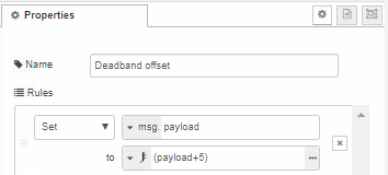
Change the +5 value to whatever you would like the deadband to be.
Lights Wattage Scaling:
This scaling is to show the approximate wattage of your lights when using the dimmer. This will require some data collection on your particular setup, and a Kill-A-Watt meter or similar. Plug the lights into the meter, and record the wattage at every 10% of PWM as you increment the slider via the dashboard. In my experience, 90-100% scales MUCH more rapidly, so I would gather wattage at 1% intervals 90-100%. Enter this data - PWM % and Wattage - into Excel, plot a X-Y scatter plot, and add a trendline as Exponential. Show the trendline equation in the graph.
Now, go into the “Scale PWM to Wattage” node:

And modify the formula to match your trendline formula. JSONata uses the markup “$power(base, exponent)” for exponential equations. The constant “e” is approximately 2.71828, which is more than precise enough for this application. So if your excel trendline formula was:
y = 32.953e0.0276x
then the JSONata expression would be:
32.953*($power(2.71828, (0.0276*(payload)))
The resulting formula in the node will look like:

Lastly, you'll have to go into the "Wattage" gauge UI element and adjust the scale min & max to reflect your lights' true minimum and maximum wattage.
Appendices:
Wiring Block Diagram

Pi Pinout Table

Dimmer Module Wiring

Ultrasonic Distance Sensor (SRF04/SRF05) Wiring
